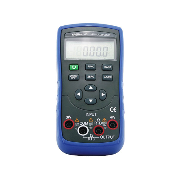
RTDs: What exactly are they?
Resistance thermometers are also known as Resistance Temperature Detectors. The RTD is just a type of temperature sensor device that uses the concept that the impedance of a metal changes when it is subject to temperature changes, and it is reflected when measuring temperature.
In practice, an electrical current is passed through a chunk of metal (the RTD component/resistor) that is located near the temperature measurement site. An analyzer then measures the RTD element’s electrical resistance. Based on the verifiable resistance properties of the RTD element, this total resistance load value is then connected to temperature(℃).
Understanding the Basics: Working of RTDs
RTDs are based on a fundamental relationship between both metallic materials and temperature. The impedance of metal to the transfer of electricity increases as its temperature is raised. The resistance value, measured in ohms (Ω), climbs as the elevation in temperature of the RTD impedance component grows. The resistivity of RTD materials is usually determined at zero degrees celsius (0°C) in ohms. The most common RTD specification is 100, which specifies that the RTD item must have a serious resistance of 100 at 0°C.
Metals used in RTDs
Due to a variety of properties, platinum is the most often used material for RTD components, including:
- Resistance to chemicals
- A relatively uniform temperature vs resistance correlation
- The temperature coefficient of impedance is big enough to give easily quantifiable change in resistance over temperature.
- Temperature resistance should not drastically alter with time due to stability.
An RTD resistor element may also be constructed from copper, nickel, or Balco.
Calibrating an RTD
It is likely that you will use the calibration technique to calibrate a medium to high accuracy RTD. The resistance of the device under test (DUT) is measured at multiple temperatures and the results are fitted to mathematical equations in characterization.
5 Steps for Calibration of an RTD
- The temperature source should contain a reference probe and the DUTs. Make sure the devices are all arranged in a radial pattern in the centre of the circle with the reference probe at its centre.
- Use the suitable 2-, 3-, or 4-wire connector to transmit the inputs to the readout(s).
- Determine the temperature by measuring the reference probe. In a perfect world, you’d use a temperature-specific interpretation or readout that could sense impedance and determine the temperature based on calibration factors previously set into the readout.
- Observe and compare the DUT’s impedance (s). The DUTs are determined using the formula as the standard probe because they are resistance gauges. It is indeed a smart option to finish the system by taking another measurement with the comparison probe.
- Fit the facts together. Data matching is a method of obtaining a set of coefficients specific to that same RTD and calibrating by solving a set of simultaneous equations containing the calibration parameters. This task can be accomplished using a variety of software applications.
Features:
- Compact, Lightweight Unit with Holster
- Selectable Temperature Output Readings (in °C / °F)
- Measurement & Simulation of RTD Types :Pt100 -200 to 850°C; Cu50 -50 to 150°C
- Resistance: 400 Ohms
Advantages:
- 9V Alkaline Battery
- Operation Manual
- Test Leads
- Traceable Calibration Certificate


