The standard calibration method has traditionally consisted of doing routine tests on any apparatus that may impact aspects such as successful control, safe operation, quality, or any other relevant criteria.
Calibration jobs need specialized expertise and financial investment in testing apparatus. Although it is not a novel idea, more sophisticated calibration approaches are now based on loop testing. When trying to obtain the highest possible level of precision, it is sometimes recommended that individual instrument calibration be carried out.
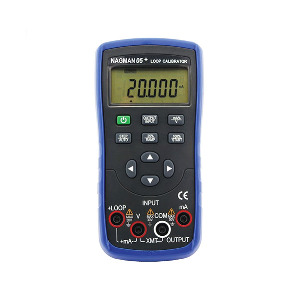
Loop Calibrator with Hart Error Analysis
Error boundaries may be difficult to calculate, and several errors are made while establishing them. A frequent perception is that process measurement tolerance should be based on a manufacturer’s specification.
To determine a practical and realistic tolerance, it is ideal for the control engineer, the quality or safety engineer, and the instrument engineer to collaborate. It is crucial to remember that the more precise the tolerance, the costlier it may be to create and maintain the measurement.
The equilibrium is midway between the needed tolerances for efficient control, the highest quality, and the greatest level of safety and the need to minimize downtime, maximize technician productivity, and use the most effective test equipment.
Modern transmitters are quite precise and give an outstanding performance; however, temperature sensors are often not as precise and, depending on the process, might display substantial drift. If a standard RTD is rated to 0.5 ° F, a process control engineer cannot anticipate better than 0.5 ° F. In actuality, although the transmitter and DCS analog-to-digital converter might be much more precise, these components give extra inaccuracy to the loop measurement. A loop error is often calculated using a statistical average or a root-mean-square (RMS) computation. Assume the RTD sensor is rated 0.5oF, the transmitter is 0.10 percent of span (span = 50oF to 250oF), and the DCS input card is 0.25 percent of span (span = 50oF to 250oF) for the temperature loop example. The error message is:
The most cautious method is to add the mistakes together (0.5 + 0.2 + 0.5 = 1.2 ° F). The final choice should also consider the importance of the measurement, the effect of the inaccuracy on the process, and the associated risks.
The conversation should not conclude here. The control engineer will strive for the lowest feasible temperature (0.75 ° F), but there are other considerations to consider. There must be an assessment of the testing equipment. The usual temperature block has an accuracy of between 0.3oF and 1oF, and it is recommended to have a test equipment-to-process measurement ratio of 4:1. A reference probe (reference or secondary primary resistance thermometers) and an accurate primary resistance thermometer are required to reduce measurement error to 0.1oF to 0.2oF for a realistic temperature simulation. Depending on the sector, this might require a substantial test equipment investment.
Multivariable Loop
Flow measurements are notoriously difficult to accomplish and often need very precise performance tolerances. When it comes to the metering of natural gas or steam, even a little inaccuracy may result in large billing issues, which in turn prompts management to examine the process with a closer eye.
A typical use of orifice metering is to adjust the measurement of differential pressure so that it is accurate by considering the process temperature and the static pressure. These three measurements may be processed by the DCS, resulting in an accurate flow computation. Despite this, differential pressure flowmeters are now available on the market. These flowmeters have an integrated RTD and static pressure measurement process, and their flow measurement output is compensated.
Pressure Loop
Checking the integrity of a pressure loop is as simple as applying pressure to the input transmitter and comparing the resulting reading to the one received from the DCS or the final control. Testing the transmitter alone may not be as successful as testing this loop calibrator with the Hart method, which may be completed very rapidly. Any batch control loop that is in use should be examined for loop testing to simplify the job of the technician and ensure that control measurements are as precise as they can be.
When testing control valves, the same method should be utilized in which an mA input into the I/P is compared to an mA output. Also included in this category are intelligent control valve positioners that use a communicator to step the valve and monitor the digital feedback.
Calibration for the Most Control
The procedures for calibrating instruments must be updated with the development of technology and automation. Although loop testing is not a novel idea, it is woefully underrepresented in the instrumentation testing industry as an effective testing method. The development of new integrated calibrating equipment has made it possible to conduct adaptable tests suitable for various applications. These tests also provide comprehensive documentation and electronic reports.
By taking a novel perspective on the Loop Calibrator with Hart, there are many chances to do more with fewer resources while maintaining or improving performance.


